EFIS
Attitude, heading, altitude, airspeed and slip/skid. The attitude indicator is being tested with sensor data. Some other readings are simulated during development.
BUILD DIARY FROM VILHELMINA
Small displays, custom electronics and plenty of hands-on testing. Follow the development of a modular system for flight instruments, navigation and engine monitoring. The project uses Waveshare touchscreens with ESP32-P4 and ESP32-S3 controllers. The 3.4-inch prototype has an 800 × 800 display. A custom piggyback board brings together GPS, CAN communications, backup battery management and sensors for altitude and airspeed.
Experimental project in development
CURRENT STATUS
Software running on prototype displays.ONE PANEL, SEVERAL JOBS
The aim is a two- or three-display panel. Each screen has its own processor and memory. The instruments can share the work, and each screen can switch views as needed.
Attitude, heading, altitude, airspeed and slip/skid. The attitude indicator is being tested with sensor data. Some other readings are simulated during development.
Pan and pinch to zoom on the vector map. Pick and adjust waypoints, save routes for reuse, or transfer flight plans and user waypoints from the phone.
A prototype view shows simulated engine readings, including manifold pressure. A separate piggyback board for engine sensors is planned.
PHOTOS FROM THE BUILD
Five views from the physical prototype show the EFIS, map, GPS, engine monitoring and Wi-Fi.
Select a photo to enlarge it.
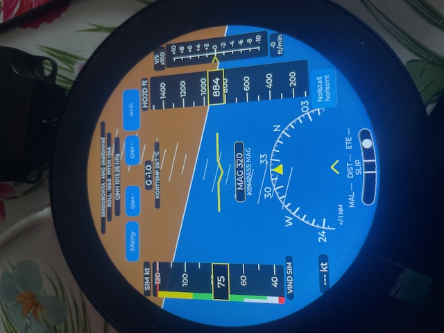
Attitude, airspeed, altitude, heading and slip on the round display.
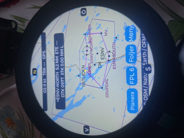
The map around Vilhelmina with waypoints and flight planning controls.
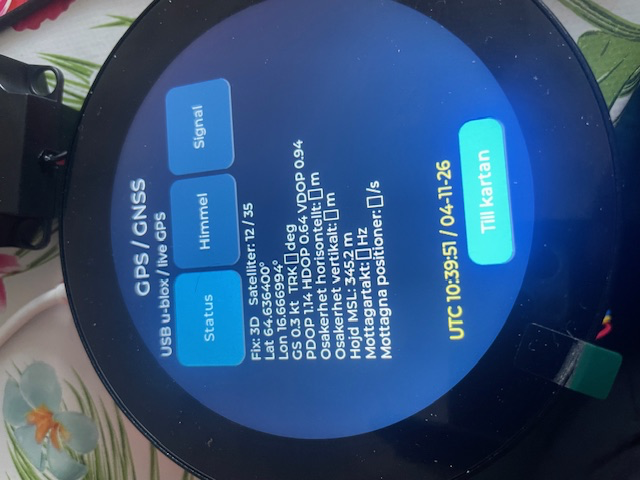
Satellite, position and receiver information from a connected u-blox receiver.
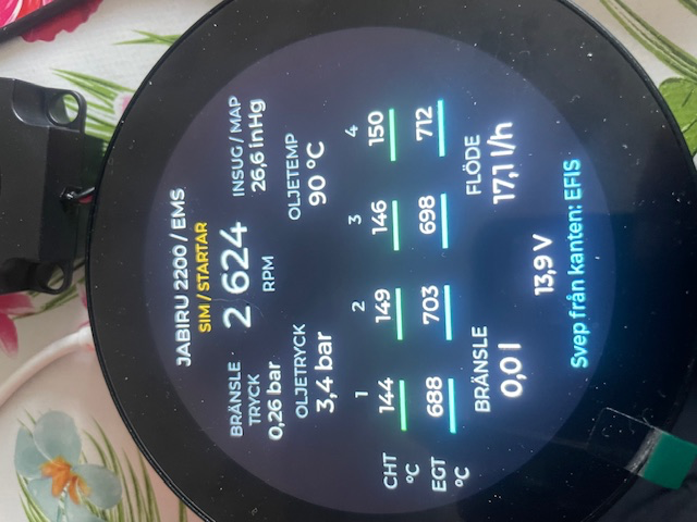
A Jabiru 2200 demo with RPM, pressures, temperatures and fuel readings. The display is labelled as a simulation.
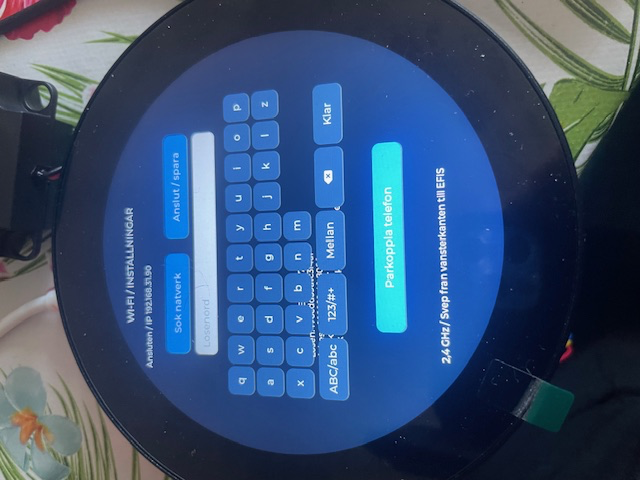
Network selection, on-screen keyboard and phone pairing.
These photos show the physical prototype. Some readings are simulated. The animations below are separate illustrations.
TAKE A CLOSER LOOK
Watch the attitude and instrument readings change as the aircraft follows a sample route around Vilhelmina. This web demo is based on the prototypes.
The graphics and update rate are adapted for the web. All instrument readings in the animation are simulated.
THE ELECTRONICS BEHIND THE DISPLAY
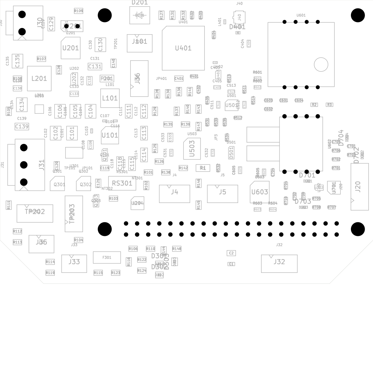
The board combines GPS, CAN, a gyroscope, an accelerometer, pressure sensors and circuitry for an external backup battery. A separately mounted magnetometer can be placed away from magnetic interference.
Revision D2 has been routed in KiCad. Manual component matching has been requested from JLCPCB. Component selection and assembly will be reviewed before the order for five prototypes is finalised.
PLAN AT HOME. TAKE IT TO THE AIRCRAFT.
The iPhone prototype overlays aviation data on Apple Maps. Build a route on the map, review and save it in the list, then transfer it to the instrument over Wi-Fi. The instrument keeps its map database on its SD card.
Enter a pairing code the first time. When the instrument is powered on and the phone is on the same Wi-Fi network or the instrument’s own network, the app can find it again and transfer saved flight plans.
Retrieving flight and engine logs and delivering software updates are possible extensions of the same setup.
The phone shown here is an illustration using the test map as its background. The iPhone app uses Apple Maps.
BUILD DIARY
We ran the EFIS and moving map side by side on a Raspberry Pi 5 with a touchscreen. Both views used simulated values. The map read its database from the Pi, and the first touch controls worked.
The test shows that we can reuse parts of the software for a possible rectangular 10-inch display with EFIS, map and EMS. The round displays remain the development priority.
Kartprov can now send the downloaded LFV release from an iPhone to the round 3.4-inch instrument over Wi-Fi. We used the instrument’s own network. The instrument verifies the package, saves it to the SD card and acknowledges the transfer. The card can stay in place throughout the update.
We tested this with Lycksele (ESNL). After transferring the data, selecting the airport on the instrument brought up LFV’s radio information. The letter ä in the Swedish Close button appeared as a box until we switched to a font that included Swedish characters.
The first version covers LFV’s radio and navigation aid information in the airport details. The base map and airspace layers are updated separately.
During a simulated flight around Vilhelmina we tried the same elevation data in two views on the round ESP32-P4 display. The map colours made higher ground easy to spot. The perspective view gave the EFIS some depth, but the terrain was too sparse to be as clear.
We put the 3D view aside to focus on a responsive EFIS and a quickly updating map. Elevation can still be added as a map layer. Performance headroom needs its own measurements.
We discussed an EMS board with inputs for thermocouples, resistive sensors, voltage signals and pulses, so the same board can support different engines. We also reviewed two proposed piggyback component substitutions. The assembler may propose a different brand for the 5 V regulator’s feedback resistor with the correct resistance and package. We will check its tolerance against the power supply requirements. Pressure sensor availability remains open.
The iPhone prototype can retrieve LFV airport information from a Raspberry Pi on the local network. A single button downloads the current release and updates airport details while preserving user waypoints and flight plans.
On the round display we tried stronger colours for land and water and extended the zoom-out range. This makes it easier to move between airport details and a wider overview.
We also requested quotes for the D2 board and the magnetometer module. Component matching continues ahead of the prototype order.
We tested the system in a moving car with the GPS antenna on the roof. The GPS page reported that EGNOS corrections were being applied. At another point it showed SBAS enabled with no corrections in use, so the indication varied during testing.
We found that returning from the satellite page left pan and pinch zoom unresponsive until we switched through the instrument view. The map was visible while the software was still in GPS mode. We loaded a fix and confirmed that both gestures worked immediately after returning to the map. This was a ground test. Position accuracy was not independently measured.
The affordable 3.4-inch ESP32-P4 displays remain the focus. We outlined a removable cover and matching cables, with a central electrical connector, a separate backup battery connector and labelled pitot and static connections. The GPS antenna will have its own SMA female bulkhead connector with a short internal coax lead. Final dimensions will be set after trial-fitting the piggyback board.
We began installation instructions for electrical wiring, pressure hoses, sensor mounting and setup. Compass work will include initial calibration and a check against known headings after installation. Once the boards arrive, testing will supply measurements and verified connections for the guide.
The first iPhone version tested a local vector map. We then switched to Apple Maps with standard, satellite and hybrid views. Airports, navigation points, airspace and user waypoints could be overlaid on the map. Routes could be drawn by tapping, reviewed in a list, saved and edited. User waypoints and routes remained local without bundling a large base map database.
Wi-Fi discovery and pairing followed. After fixing transfer and SD-card reading issues, we verified all twelve test plans and confirmed they appeared in the instrument’s library.
This was an initial sync test. Broader automation, flight and engine log analysis, and display software updates remain development work.
An M10-generation receiver now communicates directly with the 3.4-inch screen over UART using the GPIO connections planned for the piggyback board. The test receiver is a candidate for further work and uses a different module from the one specified for the board.
After troubleshooting the software and connector markings, the firmware detected 38,400 baud. GPS and the motion sensor board worked together, and we produced a clearer GPIO pin guide.
The GPS page shows position, altitude, satellites, DOP and the receiver’s reported statistical uncertainty. The uncertainty data arrived once two-way communication was working. A separate line shows whether SBAS is enabled and whether corrections are in use. It can identify EGNOS or WAAS when confirmed by the receiver. The indoor test showed SBAS enabled, with no confirmed corrections in use.
The GPS settings offer one or two updates per second. The instrument reads back the setting and shows how many positions actually arrive. We tested two updates per second and confirmed the selection was restored after a restart.
Both EFIS and map show UTC and Swedish local time, with automatic daylight saving changes. Software tests covered date rollover and time changes. Selecting a time zone from GPS position, with a manual override, was planned for a later update.
We began with a round 2.1-inch ESP32-S3 screen. The attitude indicator, moving map and swipe gestures gave us a practical starting point.
On the round 3.4-inch ESP32-P4 display we have tested the EFIS, map, GPS page and a simulated EMS view. The full system is intended to use three displays with independent processors and memory. This remains an experimental project that needs further testing.
In the iPhone prototype you can add waypoints on the map, drag them into place and review the flight plan as a list. User waypoints and saved plans can be reused.
A code pairs the phone and instrument the first time. On the same Wi-Fi or the instrument’s own network, the app can find the display again and transfer plans. We tested the transfer on the round 3.4-inch display.
The phone uses Apple Maps and the instrument keeps its own map database on the SD card. Log downloads and software updates are possible future extensions.
The D2 piggyback moved a step closer to five fully assembled prototypes. The KiCad layout includes GPS, CAN, motion sensors, a static pressure sensor and an MS4525 airspeed sensor. We ordered and paid for JLCPCB’s manual component matching.
The next step is to review component choices, availability and the assembly quote. Fabrication and assembly were still pending at this stage. Bench testing and software integration will follow delivery.
We tested EFIS and map side by side on a rectangular 5-inch ESP32-S3 screen. After fixing display stability issues, both views became readable and steady.
Map work could still pause the attitude display. The main design therefore moved towards separate displays sharing the data they need. Swiping between views remains useful. A second 3.4-inch display also received a clearly marked simulated flight around Umeå to demonstrate the map without sensors.
The round ESP32-P4 display gave us room to test GPS, the Adafruit 10-DOF board, SD-card map data and Wi-Fi together. We added waypoint selection, snapping to known points, dragging waypoints and reviewing a route in a list. Routes could start from the current GPS position or return to their first waypoint. Direct To was added too.
Pan and pinch zoom took several rounds to get right. Named plans could eventually be saved to and reopened from the SD card after a file-limit fix. The brightness setting also survived a restart.
Switching the airport detail view to vector graphics made zoomed-in drawing noticeably faster, leaving room to add labels and other details. We used a simulated flight over Arlanda to tune auto-zoom so the approach view could show the entire runway system without displaying all the taxi details.
A simulated EMS view included manifold pressure, and swipes moved between instrument functions. We also tested a 10.1-inch FMS display and added a GPS satellite view. The EMS test demonstrated the layout with simulated readings.
The small round Waveshare ESP32-S3 screen became a practical test bench. Its built-in gyroscope and accelerometer drove the attitude indicator. We corrected axis directions, calibration and drawing until roll and pitch followed the screen’s movement.
The map showed a simulated route around Vilhelmina. Touch gestures handled zoom and pan, and a swipe from the left switched between EFIS and map. A flat mode helped with testing and filming. Simulated airspeed and altitude were clearly marked.
The KiCad design had to fit the serial GPS connection, antenna clearance and the board behind the screen. Several revisions moved connectors and traces. GPS was assigned GPIO47 and GPIO48, which we later tested on the display. CAN was moved to avoid a conflict with the screen’s USB-to-serial circuitry.
At this point the work consisted of design and CAD checks. Power, backup battery and mechanical fit would be checked on the assembled prototypes.
A USB u-blox receiver provided a real position to the Mac map application. We added a GPS page with satellite, position, altitude and quality data. Two-way communication let us read the settings and confirm 1 Hz and 10 Hz before restoring the receiver’s previous 5 Hz setting.
The next step was to test the same communication directly on the ESP displays.
The original idea was to see how far we could get building our own electronic flight instrument using small ESP processors and touchscreens. The attitude display, map and flight planning would develop alongside the hardware.
Early computer tests let us work on the display and map while the hardware was still taking shape. A Raspberry Pi was used for sensor connections, and readings such as airspeed could be simulated. Each working part would then need testing on the physical instrument.
ABOUT THE BUILDER
I’m Gustav Billman and I live in Vilhelmina, Sweden. Flying, flight instruction and building my own aircraft have been a big part of my life. This is where I share the ideas, tests and lessons from the EFIS project.
Stories about flying and homebuilding from my previous website will find a home here later.
WHAT’S NEXT
The project could grow to include a dedicated EMS display. Another idea is to show nearby aircraft on the moving map. That would require a suitable traffic receiver or data source, plus development and testing.
BUILDING YOUR OWN AIRCRAFT?
I’d like to hear from experimental aircraft builders with an interest in electronics. If you build instruments, work with sensors or have ideas for the next steps, get in touch to swap experiences and discuss the project.